 |
|
 |
| Mostra argomento precedente :: Mostra argomento successivo |
| Autore |
Messaggio |
gerarcone
utente attivo

Iscritto: 04 Mgg 2004
Messaggi: 5313
Località: Roma
|
 Inviato: Lun 15 Feb, 2010 2:09 pm Oggetto: Macchine fotografiche a bordo delle sonde spaziali Inviato: Lun 15 Feb, 2010 2:09 pm Oggetto: Macchine fotografiche a bordo delle sonde spaziali |
 |
|
Mi sono sempre chiesto come funzionassero gli apparecchi fotografici a bordo delle sonde spaziali fino ad anni recenti. In particolare vari decenni fa, come si faceva a trasmettere un'immagine a terra se non esisteva il digitale?
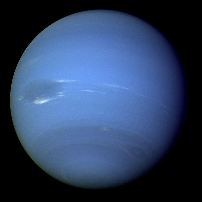
(Nettuno ripreso dal Voyager 2. Fonte: Wikipedia) |
|
Vai ad inizio pagina
Vai a fine pagina |
|
|
LucaFuma
utente attivo

Iscritto: 17 Mgg 2007
Messaggi: 1714
Località: Lecco-Milano
|
| Inviato: Lun 15 Feb, 2010 3:25 pm Oggetto: Re: Macchine fotografiche a bordo delle sonde spaziali |
|
|
| gerarcone ha scritto: | In particolare vari decenni fa, come si faceva a trasmettere un'immagine a terra se non esisteva il digitale?
|
Non esisteva il digitale?
Le prime comunicazioni elettriche sono state digitali (alfabeto morse...)

Per rispondere alla domanda, non so, forse trovavano il metodo di scansionare il negativo per poi inviare i dati via radio fino alla Terra...
Luca
_________________
Pentax K20D, SMC-DA 12-24 f4, Tamron 17-50 f2.8, Tamron 28-75 f2.8; SMC-A 50mm f1.7, SMC-A 35-105 f3.5, Cosina 100mm f3.5 macro, METZ 48AF-1
"Troppi motivi non esistono, troppi colori si confondono..." G. Ferretti |
|
Vai ad inizio pagina
Vai a fine pagina |
|
|
gerarcone
utente attivo
Iscritto: 04 Mgg 2004
Messaggi: 5313
Località: Roma
|
| Inviato: Lun 15 Feb, 2010 3:55 pm Oggetto: Re: Macchine fotografiche a bordo delle sonde spaziali |
|
|
| LucaFuma ha scritto: | | Per rispondere alla domanda, non so, forse trovavano il metodo di scansionare il negativo per poi inviare i dati via radio fino alla Terra... |
Sono quasi certo che la comunicazione via radio fosse analogica, solo che non mi spiego come facessero a riprendere le immagini.
Ah, ci sono! C'era il kit della Ornano in 3 bagni e una scimmietta che eseguiva lo sviluppo e scansionava le dia |
|
Vai ad inizio pagina
Vai a fine pagina |
|
|
Shedar
utente attivo

Iscritto: 06 Dic 2007
Messaggi: 3651
Località: Amena
|
| Inviato: Lun 15 Feb, 2010 4:23 pm Oggetto: |
|
|
http://it.wikipedia.org/wiki/Programma_Voyager
Tenete sempre a mente che le tecnologie nascono in genere proprio in vista di impieghi scientifici arditi .....solo poi han ricadute dirette per noi "consumatori". 
I sensori CCd non son certo nati dentro le canon 300D!
Circa le primissime immagini degli albori ....ebbene si! C'era una specie di kit oranano ^^
Cercate info sullo strumento "Yenisey-2" a bordo della "luna3", la sonda che negli anni 50 invio' a terra le prime immagini della faccia nascosta della luna.
P.s: riguardo la trasmissione a distanza delle immagini ......la TV è stata inventata da parecchio tempo eh! ^^
_________________
Clicca qui' se cerchi manuali di ingranditori ed accessori da camera oscura. || Clicca qui' per un database di immagini fatte con lenti e corpi di vario genere e marca. || Qui' informazioni sulle carte fotografiche in produzione. ||
Qui' se cerchi manuali di fotocamere o documentazione su accessori.||
Qui' Per trovare i tempi di sviluppo di ogni pellicola con ogni rivelatore. |
|
Vai ad inizio pagina
Vai a fine pagina |
|
|
LucaFuma
utente attivo
Iscritto: 17 Mgg 2007
Messaggi: 1714
Località: Lecco-Milano
|
| Inviato: Ven 19 Feb, 2010 12:10 pm Oggetto: Re: Macchine fotografiche a bordo delle sonde spaziali |
|
|
| gerarcone ha scritto: | Sono quasi certo che la comunicazione via radio fosse analogica, solo che non mi spiego come facessero a riprendere le immagini.
Ah, ci sono! C'era il kit della Ornano in 3 bagni e una scimmietta che eseguiva lo sviluppo e scansionava le dia |
Le prime comunicazioni radio sono state digitali: l'alfabeto morse non è altro che un codice binario: tratto-punto = 1-0
Poi si è scoperto come trasmettere "direttamente" la voce e si è aperto un mondo...
Poi la tecnologia è avanzata e si è capito che conveniva convertire tutto in digitale e trasmetterlo così, come ormai si fa ora.
Tornando alla trasmissione delle immagini, non è comunque detto che per trasmettere un'immagine serva la tecnologia digitale: il segnale TV è stato trasmesso in analogico fino a ieri (anzi, qui in Lombardia ancora oggi)
Quindi continuo a pensare che abbiano trovato un modo di scansionare elettronicamente i negativi per poi inviare il segnale via radio, in analogico probabilmente.
Luca
_________________
Pentax K20D, SMC-DA 12-24 f4, Tamron 17-50 f2.8, Tamron 28-75 f2.8; SMC-A 50mm f1.7, SMC-A 35-105 f3.5, Cosina 100mm f3.5 macro, METZ 48AF-1
"Troppi motivi non esistono, troppi colori si confondono..." G. Ferretti |
|
Vai ad inizio pagina
Vai a fine pagina |
|
|
Altaich
utente attivo

Iscritto: 21 Mar 2006
Messaggi: 1813
Località: Alba
|
| Inviato: Sab 20 Feb, 2010 1:21 am Oggetto: |
|
|
Penso che un'occhiata al programma Ranger possa essere interessante.
nota: se fai una ricerca sono sicuro trovi il pdf originale. Io l'ho qui con me e ti faccio un po' di cut and paste
Innanzitutto di cosa si trattava (voce della Wiki inglese):
Programma Ranger
Le informazioni che seguono sono prese da:
Ranger VII - Photographs of the Moon
Part I: Camera "A" Series
Chapter IV - Television System Description
- Cameras
The Ranger Block III spacecraft television system contains six
cameras, divided into two separate channels designated P and F.
Each channel is self-contained, with separate power supplies, timers,
and transmitters. All six cameras are fundamentally the same, with
differences in exposure times, fields of view, lenses, and scan rates
distinguishing the individual cameras (Table 1).

One-inch-diameter vidicons are used for image sensing. Electromagnetically
driven slit-type shutters expose the vidicons. The image
is focused on the vidicon target through the shutter, which is placed
slightly in front of the focal plane. The vidicon target is made up of a
layer of photoconductive material, initially charged by scanning with
an electron beam. The image forrned on the photoconductive surface
causes variations in resistance across the surface which are a function
of the image brightness. These variations allow a redistribution of the
charge which remains after exposure. In the Ranger cameras, the
charge pattern formed by the image on the photoconductor remains
much longer than in commercial systems, so that the pictures may
be taken more slowly. By slowing down the picture-taking rate, it
is possible to use a narrow electrical bandwidth, which simplifies
the communications problem in transmission of the signal to Earth.
After the image has been formed on the photoconductor by operation
of the shutter, an electron beam scans the surface and recharges
the photoconductor. The variation in charge current is the video
signal, which is then amplified several thousand times and sent to
the transmitter, where the amplitude variations are converted to frequency
variations. The frequency-modulated signal is amplified, and
the signals from the two channels are combined and transmitted
to Earth through the spacecraft high-gain antenna.
1. F Channel
The F channel has two cameras -the A camera with a 25" field
and the B camera with an 8.4' field. Both have 5-msec exposure times;
however, the A camera has a 25-mm f/1.0 lens, while the B camera
f/2.0 lens is 76 mm. The combined useful operating range of the two
cameras is from about 10 to 2500-ft lambert" scene brightness. This
large dynamic range allows for the possibility of the spacecraft
impacting in a region with poor lighting conditions without appreciable
reduction in the quality of the photographs. The electron beam
scans an area approximately 11mm square in 2.5 sec with 1150 lines.
The two cameras operate in sequence, so that only one camera is
being scanned at a particular time. This allows the signals from the
two cameras to be transmitted over a single transmitter. Since each
camera requires 2.5 sec to be scanned and then must wait 2.5 sec while
the other camera is scanned, there are intervals of about 5 sec between
consecutive pictures on a particular camera. During the waiting
period, the cameras erase the residual image from the preceding picture
and the shutter exposes the vidicon for the next cycle of operation.
2. P Channel
The P channel contains four cameras, designated PI through P4.
The same combination of lens types as in the F channel are used in the
P cameras. PI and P, use 76-mm f/2.0 lenses, and P, and P, use 25-mm
fD.0 lenses, so that the P cameras have the same dynamic range capability
as the F cameras. The primary difference between the two sets
of cameras is in the scan rates and the portion of the photoconductive
target used. The P cameras scan only a 2.8-mm-square segment of the
target with 300 scan lines. The time required to scan the area is 0.2 sec.
Again, as with the F cameras, only one camera is being scanned at a
time, so that all four are coupled into a single transmitter. The time
between consecutive pictures on a particular camera is 0.84 sec.
Because of the smaller target area of the P cameras, the field of view
is correspondingly smaller than that of the F cameras. PI and P, have
approximately 2.1" fields, while the P, and P4 fields are approximately
6.3". In addition to the differences described above, the P. camera
exposure times are shorter than the F exposures. The P shutters are
set for a 2-msec exposure to reduce image motion as the spacecraft
approaches the lunar surface. The last complete F camera picture is
taken between 2.5 and 5 sec before impact, while the last complete
P camera picture is taken between 0.2 and 0.4 sec because of the
faster cycling rate on the P cameras. Image motion is therefore more
severe in the last P camera pictures, and shorter exposure times are
required. The sequence for one cycle of operation of the P cameras
is PI-P,-P,-P4, so that photographs are taken alternately by a 76-mm
lens and a 25:mm lens.
- Receiving and Recording Equipment
The television signals from the spacecraft are received with 85-ftdiameter
antennas at two sites, located about 10 mi apart at Goldstone,
California. The signals are amplified and mixed by a local
oscillator to reduce the signal center frequency to 30 Mc and then sent
to the television receiver. Another mixing operation reduces the
frequency to 4.5 and 5.5 Mc, respectively, for the two channels.
The signal frequency variations are then converted back to amplitude
variations in two demodulators (one for each camera channel), whose
outputs are the same as the video signals originally generated in the
cameras. The video signals are used to control the intensity of an
electron beam in a cathode-ray tube, which is scanned in unison with
the electron beam in the cameras. The cathode-ray tube reconstructs
the original image, which is then photographed on 35-mm film. These
recording devices are similar to the commercial kinescopes used for
recording television programs on film. Again, there is one recording
device for each camera channel, so that two pictures are being
recorded at any instant in time, one F camera and one P camera. All
the functions discussed above are duplicated at both receiving sites,
with one exception. One site utilizes a single film recorder to record
the four P cameras, while the other site maintains two film recorders
and records both camera channels.
In addition to the film recorders, another means of recording the
data is used. The 4.5- and 5.5-Mc signals that go to the demodulators
are also sent to another mixer, which reduces the center frequency
still further to 500 kc. These signals are recorded on magnetic tape at
both sites. Two such recorders are used at each receiving station.
In order to obtain film records from the magnetic tapes, they are
played through a demodulator, and the video signal is applied to the
film recorder as discussed above.
- Camera Calibration
The calibration of the cameras involves three principal aspects of
camera performance: light-transfer characteristic (photometric calibration),
sine-wave response (modulation transfer function), and
system noise. In addition, data on geometric distortion are obtained.
1. Light-Transfer Characteristic
In order to obtain some absolute photometric information about the
lunar surface, camera sensitivity is measured as a function of scene
brightness. Using a set of collimators to simulate the scene, the
cameras are exposed to various brightness levels before launch, and
the camera signal output is recorded on magnetic tape. The magnetic
tape is then played back through the recording equipment at Goldstone,
and the calibration data are recorded on the same film as
the lunar photographs in order to eliminate errors due to differences
in film strips processed at different times. The variation in development
of a single strip from one end to the other is negligible. The net
result, then, is the functional relationship between film density and
collimator brightness. In order to account for the differences between
the spectral emission characteristics of the collimators and the reflected
solar radiation from the lunar scene, a series of spectral
measurements is made on all the instrumentation. A correction factor
is then calculated to correct the collimator brightness to lunar scene
brightness. Reference 5 describes this procedure. Since the photometric
calibration is on the same film as the photographic data, it can
be carried through subsequent copying operations. A typical lighttransfer
characteristic of scene brightness vs. negative film density for
a 76-mm and a 25-mm camera is shown in Fig. 6. The accuracy of the
photometric calibration is limited primarily by vidicon nonuniformities
and variations in exposure times, and is expected to be about +/-20%.

2. Sine-Wave Response
In order to obtain the approximate mathematical description of the
system required for the figure of merit, it is necessary to determine
the sine-wave response of the system. There are a number of ways of
obtaining such data. The most direct method is the use of slides with
sinusoidal variations in transmission which are then placed in the
calibration collimators to illuminate the cameras. A film recording is
made, and then the film is scanned with a microphotometer to determine
the sine-wave response. A typical response curve is shown in
Fig. 7.

3. System Noise and Geometric Distortion
Noise is one of the critical parameters of a photographic system
which is required to characterize the system. For a television system,
it is convenient to combine film granularity with electrical noise
generated in the camera and the communication system to obtain an
over-all measure of system noise. The over-all noise is measured by
scanning a film recording with a microphotometer. The resulting
record is then analyzed to calculate the root-mean-square variations
in transmission.
Geometric distortion is determined by inserting a slide in the
collimators which has been ruled horizontally and vertically. Photographs
of the slide are then used to correct the distortion.
- Film Recording and Processing
Because of the short time duration of the picture-taking sequence,
it is prudent to set up the film recorder brightness levels well in
advance of the mission. It is necessary, therefore, to make the dynamic
range of the recorder correspond to the dynamic range of the camera
system. This precludes the optimum setup for the particular lighting
conditions of the impact area; however, no information is lost permanently
because the magnetic tape can be played back after the
mission, with the film recorder setup optimized.
The optimum density range in the film is determined by several
practical characteristics of the film recorder, such as cathode-ray tube
brightness, resolution, film camera aperture, and the film itself. An
analysis of these parameters indicated that a density range of 1.6 from
scene black to scene white was the best choice in terms of minimizing
the effects of film granularity.
The film used for the Ranger VII mission was Eastman Kodak
television recording film, type 5374. The negatives were developed
by a commercial film processor to a gamma of 1.4. The processed
negatives were then contact printed in a continuous film printer to
obtain a master positive. The film used for the positive was Kodak
type 5235, a fine-grain panchromatic film. The positive was developed
to a gamma of 1.0. The photographs in this atlas were produced
from the master positive by making 8 X 10-in. negatives using an
electronic dodging device. The negatives were then used to contact
print the photographs, with some additional manual dodging in the
contact printer.
_________________
He made me suddenly realize that photographs could reach eternity through the moment. Henri Cartier-Bresson
Your decisions on whether to buy, when to buy and what to buy should depend on careful consideration of your needs primarily, with a little of your wants thrown in for enjoyment, After all photography is a hobby, even for pros. Herbert Keppler: 1925-2008 |
|
Vai ad inizio pagina
Vai a fine pagina |
|
|
|
|
Non puoi iniziare nuovi argomenti
Non puoi rispondere ai messaggi
Non puoi modificare i tuoi messaggi
Non puoi cancellare i tuoi messaggi
Non puoi votare nei sondaggi
Non puoi allegare files in questo forum
Non puoi scaricare gli allegati in questo forum
|
|


